CANopen Guide
See also: Networking and Communications
Topic Menu
CANopen Overview

|
Hands-on with CANopen and Horner OCS |
CANopen is a communication protocol and device profile specification for embedded systems used in automation. In terms of the OSI model, CANopen implements the layers above and including the network layer. The CANopen standard consists of an addressing scheme, several small communication protocols and an application layer defined by a device profile. The communication protocols have support for network management, device monitoring and communication between nodes, including a simple transport layer for message segmentation/desegmentation. The lower level protocol implementing the data link and physical layers is usually Controller Area Network (CAN), although devices using some other means of communication (such as EtherCAT) can also implement the CANopen device profile.
CANopen is a CAN-based higher layer protocol. It is developed as a standardized embedded network with highly flexible configuration capabilities. CANopen is designed for motion-oriented machine control networks, such as handling systems. It is used in various fields, such as medical equipment, off-road vehicles, maritime electronics, public transportation, building automation, etc
The CANopen communication profiles are based on the CAN Application Layer (CAL) protocol. Version 4 of CANopen (CiA DS 301) is standardized as EN 50325-4.The CANopen specification cover application layer and communication profile (CiA DS 301), as well as a framework for programmable devices (CiA 302), recommendations for cables and connectors (CiA 303-1) and SI units and prefix representations (CiA 303-2). The application-layer as well as the CAN-based profiles are implemented in software.
CANopen unburdens the developer from dealing with CAN-specific details such as bit-timing and implementation-specific functions. It provides standardized communication objects for real-time data (Process Data Objects, PDO), configuration data (Service Data Objects, SDO), and special functions (Time Stamp, Sync message, and Emergency message) as well as network management data (Boot-up message, NMT message, and Error Control).
See also: CANopen Networking Bit Rates
States and Communication Object Relations
Table below shows the relation between communication states and communication objects. Services on the listed communication objects may only be executed if the devices involved in the communication are in the appropriate communication states.
| Communication v. Communication Objects Table | ||||
|---|---|---|---|---|
| Initializing | Pre-Operational | Operational | Stopped | |
| PDO | X | |||
| SDO | X | X | ||
| Synchronization Chart | X | X | ||
| Time Stamp Object | X | X | ||
| Emergency Object | X | X | ||
| Boot-Up Object | X | |||
| Network Management Object | X | X | X | |
Nodes Any system or device connected to a network is referred to as a node.
-
CANopen trunk with termination resistors.
-
Each node must have a unique node ID, in the range of 1 to 127.
-
Maximum length depends on network speed. For example: about 250m with 250kbps.
-
The default message identifiers used by CANopen nodes are directly related to their node ID
Usually refers to the ID of the device on a supported CAN, such as CsCAN, CANopen, etc. Each device must have a unique network ID. Also called Node ID.. -
The node ID gets ’embedded’ into the message identifier on CAN using an 11-bit message identifier, the node ID is in bits 0-7.
-
Bits 8-10 contain message type information.
-
IDs not listed are free and may be used by system integrator.
Default CAN message identifiers and an example for Node ID 5 for messages in CANopen network is as shown in table below:
|
If CANopen Node ID = 5 |
|||
|
From |
To |
Communication objects |
Message Identifier |
|
0h |
|
NMT Service |
0h |
|
80h |
|
SYNC Message |
80h |
|
81h |
FFh |
Emergency Message |
85h |
|
100h |
|
Time Stamp Message |
100h |
|
181h |
1FFh |
1st Transmit PDO |
185h |
|
201h |
27Fh |
1st Receive PDO |
205h |
|
281h |
2FFh |
2nd Transmit PDO |
285h |
|
301h |
37Fh |
2nd Receive PDO |
305h |
|
381h |
3FFh |
3rd Transmit PDO |
385h |
|
401h |
47Fh |
3rd Receive PDO |
405h |
|
481h |
5FFh |
4th Transmit PDO |
485h |
|
501h |
57Fh |
4th Receive PDO |
505h |
|
581h |
5FFh |
Transmit SDO |
585h |
|
601h |
67Fh |
Receive SDO |
605h |
|
701h |
77Fh |
NMT Error Control |
705h |
Return to the Top: CANopen Guide
CANopen Features
|
|
XLE, XLT, XLEe, XLTe |
X5, XL4, EXL6, EXLW, XL7, EXL10, XL15+, RCC1410, RCC2414, RCC972, RCC8842 |
|
125K, 250K, 500K & 1M bps |
||
|
11 Bits |
||
|
Master & Slave Modes |
||
|
Transmit
Process Data Objects (TPDO) : supports 64 PDO's |
||
|
Static
PDO : supports 64 PDO's |
||
|
Asynchronous Synchronous |
||
|
COB-ID, Transmission Type & Timing Parameters |
||
|
Expedited Upload, Expedited Download & Segmented Upload |
||
|
Supported only in Generic Error |
||
|
Supports up to 127 slaves |
||
|
Application Layer supported |
CiA 301 v 4.02 |
|
|
CiA 405 v 2.00 |
||
|
Pass through mode and Remote mode Note: If Node is busy with boot up reconfiguration then CsCAN pass through mode will not work. |
||
|
Allows addition of 16 slave nodes |
Allows addition of 126 slave nodes |
|
|
Node
Guard Protocol: 16 Nodes |
Node
Guard Protocol: 127 Nodes. |
|
|
Server:16 |
Server:
128 |
|
|
Supported from firmware version 12.81 onwards |
Supported |
|
CANopen Networking Bit Rates
-
10 kbps
-
20 kbps
-
50 kbps
-
125 kbps
-
250 kbps
-
500 kbps
-
800 kbps
-
1000 kbps
Return to the Top: CANopen Guide
CANopen Status Registers
CANopen master and slave status registers is 64 bits and details are as below:
|
Bits |
Error |
Reason |
Indication |
Remedy |
EMCY Object |
Applicable |
|
|
Master |
Slave |
||||||
|
1 |
Invalid or corrupt CANopen configuration can cause this error. Configuration of any COB-ID with value ’0’ (with or without disable option selection) can also cause this error to happen. |
No CANopen communication at all, status register will be updated only if firmware finds configured status register address is valid. |
Download new configuration with COB-ID other than zero. |
N/A |
|
|
|
|
2 |
Node
ID |
This error will be flagged if firmware finds invalid Node-id value, i.e. zero or greater than 127. The corrupt configuration can also cause this error to happen. |
Firmware will ignore downloaded configuration and will refer default internal slave configuration. |
Download new configuration. |
This error will trigger valid EMCY Object with status register value in ’Manufacturer Specific Error Field’ of message. |
|
|
|
3 |
If any of (i.e. Node Guard or Heartbeat) error control protocol is not configured and node configured is single slave. |
CANopen communication will work as normal but Master node will not be able to detect some of the slave failures. |
The user can configure any of Error control protocol. |
This error will not trigger EMCY Object. |
X |
|
|
|
4 |
Baud rate mismatch, CAN network without proper terminating resistor, improper CAN network cabling can cause this error. |
CANopen communication might not work properly. |
Verify configured baud rate, check for proper terminating resistor and cabling. |
This error will trigger valid EMCY Object with status register value in ’Manufacturer Specific Error Field’ of message. |
|
|
|
|
5 |
This error is disabled and indicated by other bits (collectively indicated by Bits 6,7,8 & 9) |
N/A. |
N/A. |
N/A. |
N/A
|
||
|
6 |
Firmware is not able to set the configured internal register value. |
RPDO data will not get updated in the register. The RPDO index value which is having error will be updated in status register. |
Verify configured index value, index value should be within supported range and with read/write access. |
This error will trigger valid EMCY Object with status register value in ’Manufacturer Specific Error Field’ of message. |
|
|
|
|
7 |
Configured RPDO object index value is out of range or not supported by the firmware. |
RPDO data will not get updated in the register. The RPDO index value which is having error will be updated in status register. |
Verify configured index value, index value should be within supported range. |
This error will trigger valid EMCY Object with status register value in ’Manufacturer Specific Error Field’ of message. |
|
|
|
|
8 |
Configured RPDO object count (or data length) does not match with received RPDO message. The received RPDO might have less number of objects (or different data length object) compared to configured one. |
RPDO data will not get updated in the register. The RPDO index value which is having error will be updated in status register. |
Verify RPDO object count and data length of each object with that of actual RPDO message on bus. |
This error will trigger valid EMCY Object with status register value in ’Manufacturer Specific Error Field’ of message. |
|
|
|
|
9 |
RPDO is configured without any objects. |
RPDO data will not get updated in the register. The RPDO index value which is having error will be updated in status register. |
Verify RPDO object mapping and configure as per the requirement. |
This error will trigger valid EMCY Object with status register value in ’Manufacturer Specific Error Field’ of message. |
|
|
|
|
10 |
This error is disabled and indicated by other bits (Collectively indicated by Bits 11, 12, 13 & 14). |
N/A |
N/A |
N/A |
N/A
|
||
|
11 |
Firmware is not able to get the configured internal register value. |
Configured TPDO will not be sent. The TPDO index value which is having error will be updated in status register. |
Verify configured index value, index value should be within supported range and with read access. |
This error will trigger valid EMCY Object with status register value in ’Manufacturer Specific Error Field’ of message. |
|
|
|
|
12 |
Firmware is not able compose the configured TPDO. |
Configured TPDO will not be sent. The TPDO index value which is having error will be updated in status register. |
Verify configured index value, index value should be within supported range and with read access. Also corrupt TPDO configuration can cause this error, in such case reload the CANopen configuration. |
This error will trigger valid EMCY Object with status register value in ’Manufacturer Specific Error Field’ of message. |
|
|
|
|
13 |
Configured TPDO object index value is out of range or not supported by the firmware. |
Configured TPDO will not be sent. The TPDO index value which is having error will be updated in status register. |
Verify configured index value, index value should be within supported range. |
This error will trigger valid EMCY Object with status register value in ’Manufacturer Specific Error Field’ of message. |
|
|
|
|
14 |
TPDO is configured without any objects. |
Configured TPDO will not be sent. The TPDO index value which is having error will be updated in status register. |
Verify TPDO object mapping and configure as per the requirement. |
This error will trigger valid EMCY Object with status register value in ’Manufacturer Specific Error Field’ of message. |
|
|
|
|
15 |
Received SDO message is with invalid byte count, i.e. count is not equal to 8. |
SDO request or response will not be processed. |
Verify SDO message generated by the node, if byte count is not equal to 8 then the node is not valid CANopen device. |
This error will not trigger EMCY Object. |
|
|
|
|
16 |
Received NMT message is with invalid byte count, i.e. count is not equal to 2. |
NMT request will not be processed. |
Verify NMT message generated by the node, if byte count is not equal to 2 then the node is not valid CANopen device. |
This error will trigger valid EMCY Object with status register value in ’Manufacturer Specific Error Field’ of message. |
X |
|
|
|
17 |
Status register address is not configured or address is invalid. |
CANopen node status will not be available. |
Configure valid status register address. |
This error will not trigger EMCY Object. |
|
|
|
|
18 |
Node guard message request from Master is not received within configured time. It is also called as ’Node Life Time Error’. |
Slave will set error, but continues with normal operation. |
Verify node guard time configured in Master Configuration. |
This error will trigger valid EMCY Object with status register value in ’Manufacturer Specific Error Field’ of message. |
X |
|
|
|
19 |
Node is configured for Heartbeat message consumption and heartbeat message from producer is not received within configured consume time. |
Node will set error, but continue with normal operation. But in case of Master node action to be taken can be configured. |
Verify Heartbeat consume time configured in the node, it should be greater than the producer time. Check whether producer node is configured for Heartbeat message production as required interval. |
This error will trigger valid EMCY Object with status register value in ’Manufacturer Specific Error Field’ of message. |
|
|
|
|
20 |
One of configured non mandatory slave is failed. |
Master will set error, but continue with normal operation. If all slaves in the network are failed then master node doesn’t allow NMT state transition. Master node can be configured to reinitialize boot up process of slave node on error. |
Check CAN cabling, Error control protocol configuration in slave and master node and power status of slave node etc. |
This error will trigger valid EMCY Object with status register value in ’Manufacturer Specific Error Field’ of message. |
|
X |
|
|
21 |
One of configured mandatory slave is failed. |
Master will set error and try to reconfigure entire network or stop entire network based upon the user configuration. |
Check CAN cabling, Error control protocol configuration in slave and master node and power status of slave node etc. |
This error will trigger valid EMCY Object with status register value in ’Manufacturer Specific Error Field’ of message. |
|
X |
|
|
22 |
Number of CAN messages received per second are more than the limit of CAN hardware and firmware. |
CANopen communication is not guaranteed. |
Check the CAN bus load, it should be around 80%. Also check CAN cable wiring and terminating resistor. |
This error will trigger valid EMCY Object with status register value in ’Manufacturer Specific Error Field’ of message. |
|
|
|
|
23 |
One of CAN controller error state entered when it detects more than 256 CAN errors. |
No CANopen communication. |
Check for proper terminating resistor and CAN wiring. Requires power reset to start new CANopen communication. |
N/A |
|
|
|
|
24 |
One of CAN controller error state entered when it detects more than 127 CAN errors, but less than 256. Unplugging CAN network cable can cause this error. |
No CANopen communication |
Check for proper terminating resistor , CAN wiring and firm connection CAN connector to device |
N/A |
|
|
|
|
25 -32 |
The 8 bit displays CANopen NMT state of device. It can have following different values. 127(Decimal) - 0x7F (Hex) - Preoperational State 005(Decimal) - 0x05 (Hex) - Operational State 004(Decimal) - 0x04 (Hex) - Stop State |
N/A |
N/A
|
N/A
|
N/A
|
||
|
33-48 |
Failed TPDO array Index (Updated only in case of any TPDO errors and array index will start with value 0). |
N/A |
N/A |
N/A |
N/A |
||
|
49-64 |
Failed RPDO array Index (Updated only in case of any RPDO errors and array index will start with value 0). |
N/A
|
N/A
|
N/A
|
N/A |
||
Master Node will have additional status of each Slave Node following 64-bits long Status register. One 16bits register will be dedicated to indicate status of single slave node.
Format:
Bit 0 to 7: Error Code
Bit 8 to 15: Node-ID
Return to the Top: CANopen Guide
CANopen Error Codes
|
Error Code Values |
Error Description |
|
0 |
No error. |
|
1 |
The slave no longer exists in the Network list |
|
2 |
No response on access to Actual Device Type (object 1000h) received |
|
3 |
Actual Device Type (object 1000h) of the slave node did not match with the expected Device Type Identification in object 1F84h |
|
4 |
Actual Vendor ID (object 1018h) of the slave node did not match with the expected Vendor ID |
|
5 |
Slave node did not respond with its state during Check node state -process. Slave is a heartbeat producer |
|
6 |
Slave node did not respond with its state during Check node state -process. Slave is a Node Guard slave (NMT slave) |
|
7 |
It was requested to verify the application software version, but the expected version date and time values were not configured |
|
8 |
Actual application software version Date or Time did not match with the expected date and time values. Automatic software update was not allowed |
|
9 |
Actual application software version Date or Time did not match with the expected date and time values and automatic software update failed |
|
10 |
Automatic configuration download failed |
|
11 |
The slave node did not send its heartbeat message during Start Error Control Service although it was reported to be a heartbeat producer |
|
12 |
Slave was initially operational. (CANopen manager may resume operation with other nodes) |
|
13 |
Actual Product Code (object 1018h) of the slave node did not match with the expected Product Code |
|
14 |
Actual Revision Number (object 1018h) of the slave node did not match with the expected Revision Number |
|
15 |
Actual Serial Number (object 1018h) of the slave node did not match with the expected Serial Number in object |
|
244 |
Error Configuring Error Control Protocol (Either Node Guard or Heart Beat) parameters |
|
245 |
Error Configuring SYNC Protocol parameters |
|
246 |
Error Configuring Time-Stamp Protocol parameters |
|
247 |
Error Configuring Emergency (EMCY) protocol parameters |
|
248 |
Error Configuring RPDO communication parameters |
|
249 |
Error Configuring RPDO Mapping parameters |
|
250 |
Error Configuring TPDO communication parameters |
|
251 |
Error Configuring TPDO Mapping parameters |
|
252 |
Error Configuring SDO protocol parameters. |
|
253 |
Invalid NMT state (Mismatch between Master NMT state and that slave NMT state) |
|
254 |
Received Emergency Object |
|
255 |
Unknown Error/ Master Reconfiguration is Active |
Return to the Top: CANopen Guide
CANopen Elements
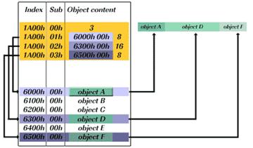
Device Model Overview
Any CANopen![]() A CAN-based communication system. It comprises higher-layer protocols and profile specifications. CANopen has been developed as a standardized embedded network with highly flexible configuration capabilities. device can be seen as a generic device.
This generic device is connected to CAN on one side and connected to application
specific I/O data on the other side. The application is the key knowledge
of the device manufacturer. The interface between the application and
CAN is realized by an object dictionary. The object dictionary is unique
for any CANopen device and represents the whole access to its implemented
application in terms of data as well as in terms of configuration. To
gain access to the object dictionary each CANopen device has to realize
a CANopen protocol stack. This CANopen protocol stack is a piece of software,
which normally is implemented on the same controller that is used by the
application software.
A CAN-based communication system. It comprises higher-layer protocols and profile specifications. CANopen has been developed as a standardized embedded network with highly flexible configuration capabilities. device can be seen as a generic device.
This generic device is connected to CAN on one side and connected to application
specific I/O data on the other side. The application is the key knowledge
of the device manufacturer. The interface between the application and
CAN is realized by an object dictionary. The object dictionary is unique
for any CANopen device and represents the whole access to its implemented
application in terms of data as well as in terms of configuration. To
gain access to the object dictionary each CANopen device has to realize
a CANopen protocol stack. This CANopen protocol stack is a piece of software,
which normally is implemented on the same controller that is used by the
application software.
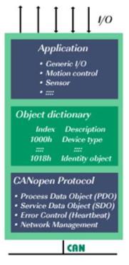
The CANopen protocol stack consists of different functions for different purposes.
-
Process Data Object (PDO) is used to transmit the application data. The application data is transmitted without any protocol overhead in broadcast.
-
Service Data Object (SDO) is used to gain access to all device parameters. SDO is used for direct device to device communication.
-
Error Control is used to validate that any device is working properly in terms of CANopen communication.
-
Network Management is used to control the network in terms of CANopen communication and indirectly in terms of system behavior.
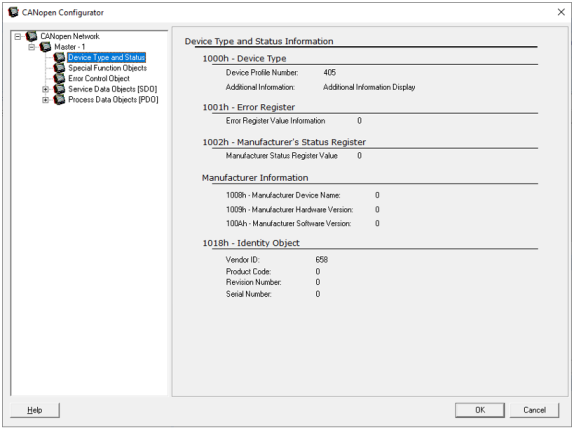
Device Type and Status
This dialog displays the device type information such as Device Type, Error Register, Manufacturer information etc. which is loaded from EDS file in the CANopen Configurator. See EDS File.
Return to the Top: CANopen Guide
Process Data Objects (PDO)
Process Data Object Protocol Overview
"Process Data Object" protocol is used to process real time data among various nodes. It can transfer up to 8 bytes (64 bits) data in one PDO either from or to the device. One PDO can contain multiple object dictionary entries. The objects within one PDO are configurable using the mapping parameter object dictionary entries. Process Data Objects (PDOs) are mapped to a single CAN frame using up to 8 bytes of the data to transmit application objects. Each PDO has a unique identifier and is transmitted by only one node, but it can be consumed by more than one node.
There are two kinds of PDOs:
1. TPDO (Transmit PDO): for data coming from the device.
2. RPDO (Receive PDO): for data going to the device.
For example, with RPDO the user can send data to the device and with TPDO the user can read data from the device. PDOs can be sent synchronously or asynchronously.
PDO transmissions may be driven by an internal event, by an internal timer, by remote requests or by the Sync message received.
-
Event- or timer-driven: An event (specified in the device profile) triggers message transmission. An elapsed timer additionally triggers the periodically transmitting nodes.
-
Remotely requested: Another device may initiate the transmission of an asynchronous PDO by sending a remote transmission request (remote frame)
-
Synchronous transmission:
-
In order to initiate simultaneous sampling of input values of all nodes, a periodically transmitted Sync message is required. Synchronous transmission of PDOs takes place in cyclic and acyclic transmission mode. In Cyclic transmission the node waits for the Sync message, after which it sends its measured values. Its PDO transmission type number (1 to 240) indicates the Sync rate it listens to (how many Sync messages the node waits before the next transmission of its values).
-
A cyclically transmitted synchronous PDOs are triggered by a defined application-specific event. The node transmits its values with the next Sync message but will not transmit again until another application-specific event has occurred.
-
In case of Synchronous RPDO messages values are updated only after reception of Sync message. i.e, In first sync, PDO messages will be sent from the transmitter and on next sync, PDO message values will be updated in the receiver though it might have received PDO message much before arrival of synch message.
-
-
Asynchronous
1. Lacking a regular time relationship; not related through repeating time patterns.
2. Not dependent on the scan rate of the OCS.
3. Contrasted with Synchronousmessages are sent after internal or external
trigger and Synchronous PDOs are sent after the SYNC message. For
example, you can make a request to a device to transmit TPDO that
contains data you need by sending empty TPDO with RTR flag (if the
device is configured to accept TPDO requests).
With RPDOs you can, for example, start two devices simultaneously. You only need to map the same RPDO into two or more different device and make sure those RPDOs are mapped with the same COB ID. See also: PDO Mapping Parameter
The predefined PDO mapping shall be used according to the appropriate profile. Each new subindex shall be filled into the corresponding predefined PDO. This way up to 8 byte of digital input data, 8 bytes of digital output data, 4 analogue inputs and 4 analogue outputs may be mapped. More data may be mapped to additional PDOs. Since they are not pre-defined and since their COB-IDs shall be marked as invalid, their usage shall be switched free on boot-up. In systems using the pre-defined connection set, the application performs this task and will know the appropriate usage of the additional PDOs. In more complex systems, a configuration shall be created that includes configuration of the mapping. In that case the configuration manager has the task of enabling all PDOs. Using predefined PDOs requires the knowledge of the corresponding mapping entries. Since this mapping depends on the extension modules it can not be entered in the EDS. A generic method that fulfills all possible cases will be very complex.
PDO Mapping Parameter
The PDO Mapping parameter defines the content of the Process Data Object.
-
The default mapping of application objects as well as the supported transmission mode is described in the Object Dictionary for each PDO.
-
PDO identifiers should have high priority to guarantee a short response time.
-
PDO transmission is not confirmed.
-
The PDO mapping defines which application objects are transmitted within a PDO (i.e. for PLC based system, Register values are sent over PDOs e.g. %R50,%R100 etc )
-
It describes the sequence and length of the mapped application objects.
-
Per default, each node has access to 8 PDOs (provided there are 127 nodes in the network), messages with process data in them
-
4 Transmit PDOs (TPDO)
-
4 Receive PDOs (RPDO)
-
-
Per default, all transmit PDOs are received and handled ONLY by the master.
-
Per default, ONLY the master is allowed to use the CAN message IDs used to transmit PDOs, so it’s only the master who can send data to the nodes.
-
With dynamic linking, PDOs are re-assigned
-
Nodes can be configured to
-
Use specific CAN IDs for transmit PDOs
-
Listen to specific CAN IDs for receive PDOs
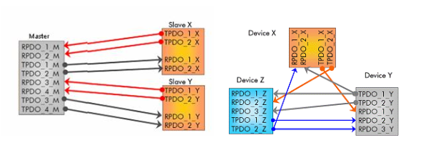
Predefined PDO Connections Dynamic PDO Linking
Process Data Objects (PDO) Configuration
Home > Hardware Configuration >CAN1 >Config will open the CANopen![]() A CAN-based communication system. It comprises higher-layer protocols and profile specifications. CANopen has been developed as a standardized embedded network with highly flexible configuration capabilities. Configurator, see below. "Process Data Object" protocol is used to process real time data among various nodes. It can transfer up to 8 bytes (64bits) data in one PDO either from or to the device. One PDO can contain multiple object dictionary entries. The objects within one PDO are configurable using the mapping parameter object dictionary entries. Process Data Objects (PDOs) are mapped to a single CAN frame using up to 8 bytes of the data to transmit application objects. Each PDO has a unique identifier and is transmitted by only one node, but it can be consumed by more than one node.
A CAN-based communication system. It comprises higher-layer protocols and profile specifications. CANopen has been developed as a standardized embedded network with highly flexible configuration capabilities. Configurator, see below. "Process Data Object" protocol is used to process real time data among various nodes. It can transfer up to 8 bytes (64bits) data in one PDO either from or to the device. One PDO can contain multiple object dictionary entries. The objects within one PDO are configurable using the mapping parameter object dictionary entries. Process Data Objects (PDOs) are mapped to a single CAN frame using up to 8 bytes of the data to transmit application objects. Each PDO has a unique identifier and is transmitted by only one node, but it can be consumed by more than one node.
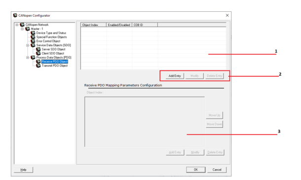
-
Configured PDO list.
-
Click to Add, Modify, Delete new PDO entry.
-
Configured Mapping parameters.
Selecting Add Entry button will open dialog below:
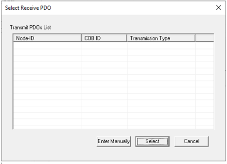
If any transmit PDO is configured it will be shown in the list, user can select that or select Enter Manually to configure PDO parameters.
Receive PDO Communication Parameters (RPDO)
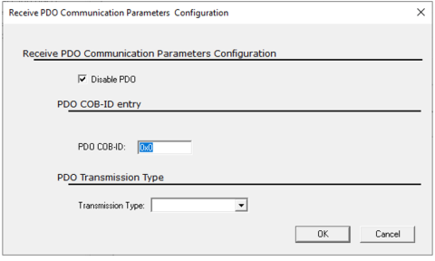
Disable PDO: By default, PDO is disabled, so uncheck this to enable PDO.
PDO COB-ID Entry:
-
PDO COB-ID: Configure required 11-bit COB-ID in this field.
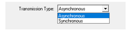
PDO Transmission Type: Select type of PDO receive method (Depends upon actual transmission type)
-
Asynchronous
1. Lacking a regular time relationship; not related through repeating time patterns.
2. Not dependent on the scan rate of the OCS.
3. Contrasted with Synchronous: Messages are transmitted after any data changes. -
Synchronous
In step or in phase, as applied to two or more circuits, devices, or machines. Contrasted with Asynchronous.: Messages are transmitted after reception of Sync message.
NOTE:In case of Synchronous RPDO messages, values are updated only after reception of Sync message. i.e., in first sync, PDO messages will be sent from the transmitter and on next sync, PDO message values will be updated in the receiver though it might have received PDO message much before arrival of a sync message.
Once the above configuration is complete, user can view the added PDO in the PDO list as shown below:
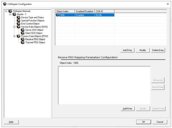
Add Entry: The user can add mapping register/variable. This will add an entry against the item selected in the list on the top
Modify: This button is used to modify any existing PDO mapping parameter This button will work only if an item in the box is selected
Delete: It is used to delete existing PDO mapping parameter. This button will work only if an item in the box is selected.
Select the PDO and then click the Add Entry button in Receive PDO Mapping Parameter Configuration to enter RPDO mapping parameters.
Receive PDO Mapping Parameters
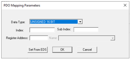
-
Data Type:Select the Data Type for the Register / Variable
-
Register Address: Configure local mapping register.
-
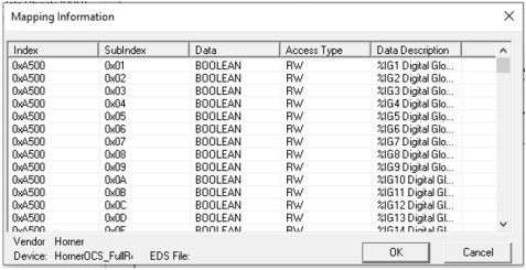
Set From EDS: This button will launch a dialog box containing different values that can be used as valid entry for mapping data. All the available information will be populated in the list box as seen in the Fig. below. Once the user selects an object from the list box Mapping Information and clicked OK, the values will automatically be populated in the index and sub Index edit box of the PDO mapping parameter configurations. User also can directly enter register/variable and then index and sub-index of the register/variable automatically populated.
NOTES:
-
Single PDO can take up to 4 -16-bit objects, or 8 – 8-bit Objects or 2-32 Objects and vice versa
-
The user can directly map OCS register/Variable to PDOs, conversion of OCS native register index to CANopen index and vice versa is taken care by Configurator.
Transmit PDO Communication Parameters
![]()
Disable PDO: By default, PDO is disabled and uncheck to enable PDO
PDO COB-ID Entry
-
PDO COB-ID: Configure required 11-bit COB-ID in this field.
-
Allow RTR: Select this option if PDO needs to be transmitted on Remote request
PDO Transmission Type
Select type of PDO transmission method, Asynchronous![]() 1. Lacking a regular time relationship; not related through repeating time patterns.
2. Not dependent on the scan rate of the OCS.
3. Contrasted with Synchronous or Synchronous
1. Lacking a regular time relationship; not related through repeating time patterns.
2. Not dependent on the scan rate of the OCS.
3. Contrasted with Synchronous or Synchronous![]() In step or in phase, as applied to two or more circuits, devices, or machines. Contrasted with Asynchronous..
In step or in phase, as applied to two or more circuits, devices, or machines. Contrasted with Asynchronous..
Asynchronous On Change configuration: On change, data are transmitted as soon as value changes.
Asynchronous On Trigger configuration: On Trigger type requires trigger bit to be configured. PDO is transmitted when trigger Bit is set to High. On successful transmission firmware resets trigger bit to Low
Asynchronous On RTR configuration: PDO is transmitted on RTR (PDO must be enabled for RTR). NOTE: On RTR type will be displayed in the drop down only if Allow RTR is enabled.
Synchronous On Change configuration: PDO is transmitted on change of message data and after reception of Sync message within sync window time. If the synchronous window length expired all synchronous TPDOs will be discarded.

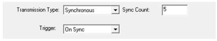
Synchronous on Sync Count configuration: PDO is transmitted on reach of ’n’ sync count within sync window time
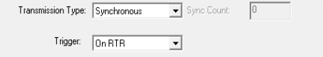
Synchronous On RTR configuration: PDO is transmitted on RTR (PDO must be enabled for RTR) and after reception of Sync message within sync window time
PDO Timing Parameter
-
Event Time: Configure event time for asynchronous messages in ms. Zero if not used. An elapsed timer additionally triggers the periodically transmitting nodes.
-
Inhibit Time: Inhibit time of a data object defines the minimum time that has to elapse between two consecutive invocations of a transmission service for that data object. Configure inhibit time for asynchronous messages in ms. Zero if not used.
Return to the Top: CANopen Guide
Service Data Object (SDO)
Service Data Object (SDO) Overview
Service Data Objects are designed to access entries in device object dictionary. By default, SDOs are configured automatically. Each node will support single Server SDO and additional server SDOs can be configured. Client SDOs are supported only in Master.
-
Used for Point-To-Point communication between a configuration tool or master/manager and the nodes.
-
It allows complete access to all entries in the Object Dictionary of a node
-
Includes all process data
-
-
Confirmed communication mode
-
Each request gets a response
-
-
Supports transfer of long data blocks such as upload or download of code blocks.
-
Up to 7 bytes per message, every message confirmed by receiver.
-
Special ”block transfer mode” allows transmitting blocks of messages with just one confirmation.
1. The SDO transport protocol allows transmitting objects of any size.
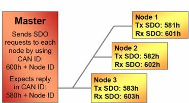
Default CAN IDs used for SDO Communication
-
The first byte of the first segment contains the necessary flow control information including a toggle bit to overcome the well-known problem of doubly received CAN frames.
-
The next three byte of the first segment contains index and sub-index of the Object Dictionary entry to be read or written.
-
The last four byte of the first segment is available for the user data.
-
The second and the following segments (using the very same CAN identifier) contain the control byte and up to seven byte of the user data.
2. The receiver confirms each segment or a block of segments, so that a peer-to-peer communication (client/server) takes place.
SDO Configuration
Home > Hardware Configuration >CAN1 >Config will open the CANopen Configurator, see below. Service data objects are designed to access entries in device object dictionary. By default, SDOs are configured automatically. Each node will support single Server SDO and additional server SDOs can be configured. Client SDOs are supported only in Master. NOTE: For every new slave device added in Master Configuration a new SDO client gets created in Master and default server SDO gets created in Slave Node. These SDO creation happen by default in configuration and user need not take care anything here. These default SDO clients and server are created for Slave reconfiguration purpose.
Server Data Objects - Server / Client
-
Server SDO: The Server SDO receives the SDO messages from the corresponding Client SDO and responses each SDO message or a block of SDO messages (SDO block transfer).
-
Client SDO: The Client SDO initiates the SDO communication by means of reading or writing to dictionary of the SDO server device
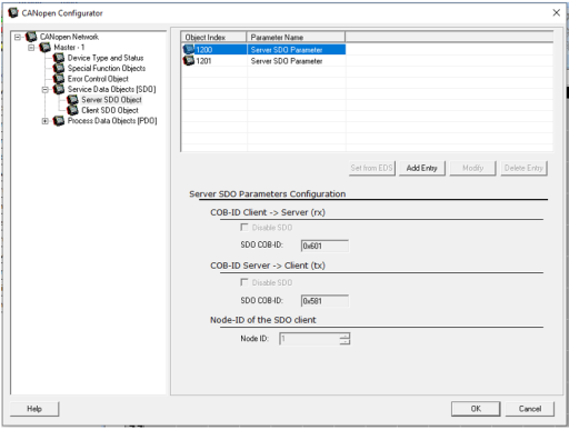
Server SDO and Client SDO will have the following buttons with same functionality. Except Add Entry button all the other 3 buttons will remain disabled until the user selects any object in the list.
Add Entry: To add an entry in the list
Delete Entry: To delete an entry in the list
Modify: To modify an entry already existing in the list
Add Entry: Disabled in Client SDO Parameters
COB ID Client --> Server (rx):
-
Disable SDO: Select this option to disable configured SDO
-
SDO COB-ID: Configure required 11-bit COB-ID in this field
COB ID Server --> Client (tx):
-
Disable SDO: Select this option to disable configured SDO
-
SDO COB-ID: Configure required 11-bit COB-ID in this field.
Node ID![]() Usually refers to the ID of the device on a supported CAN, such as CsCAN, CANopen, etc. Each device must have a unique network ID. Also called Node ID.: Enter the node ID of the SDO Client.
Usually refers to the ID of the device on a supported CAN, such as CsCAN, CANopen, etc. Each device must have a unique network ID. Also called Node ID.: Enter the node ID of the SDO Client.
Return to the Top: CANopen Guide
Network Management (NMT)
NMT Overview
The Network Management is node oriented and follows
the Master slave structure. NMT objects are used for executing NMT services.
Through NMT services, nodes are initialized, started, monitored, reset,
or stopped. All nodes are regarded as NMT slaves. An NMT slave is uniquely
identified in the network by its node id![]() Usually refers to the ID of the device on a supported CAN, such as CsCAN, CANopen, etc. Each device must have a unique network ID. Also called Node ID., a value in the range of (1...127).
NMT requires that one device in the network fulfills the function of the
NMT master.
Usually refers to the ID of the device on a supported CAN, such as CsCAN, CANopen, etc. Each device must have a unique network ID. Also called Node ID., a value in the range of (1...127).
NMT requires that one device in the network fulfills the function of the
NMT master.
The NMT protocols are used to issue state machine change commands (ie. to start and stop the devices), detect remote device bootups and error conditions. The Network Management objects include Boot-up message, Heartbeat protocol, and NMT message. Boot-up message and Heartbeat protocol are implemented as single CAN frames with 1-byte data field. The NMT message transmitted by the NMT master forces the nodes to transit to another NMT state. The NMT message is mapped to a single CAN frame with a data length of 2 byte. Its identifier is 0. The first byte contains the command specifier and the second contains the Node-ID of the device that must perform the command (In the case of Node-ID 0 all nodes have to perform the command).
NMT Services
Module Control Services: Through module control services, the NMT master controls the state of the NMT slaves. The state attribute is one of the values (Initializing, pre-operational, operational, stopped). The services can be performed with a certain node or with all nodes simultaneously.
Error Control Services: Through Error control services the NMT detects failures in a CAN-based Network. Local errors in a node may e.g. lead to a reset or change of state. Error Control services are achieved principally through periodically transmitting of messages by a device. There exist two possibilities to perform Error Control i.e., Node Guard and Heart Beat Error Control.
Bootup Service: Through this service, the NMT slave indicates that a local state transition occurred from the state INITIALISING to the state PRE-OPERATIONAL.
The CANopen![]() A CAN-based communication system. It comprises higher-layer protocols and profile specifications. CANopen has been developed as a standardized embedded network with highly flexible configuration capabilities. state machine specifies the states Initialization,
Pre-Operational, Operational and Stopped. After power-on, each CANopen
device is in the state Initialization and automatically transits to the
state Pre-operational. In this state, transmission of SDOs is allowed.
If the NMT master has set one or more nodes into the state Operational,
they are allowed to transmit and to receive PDOs. In the state Stopped
no communication is allowed except that of NMT objects. A device sends
the Boot-up message to indicate to the NMT master that it has reached
the state Pre-operational.
A CAN-based communication system. It comprises higher-layer protocols and profile specifications. CANopen has been developed as a standardized embedded network with highly flexible configuration capabilities. state machine specifies the states Initialization,
Pre-Operational, Operational and Stopped. After power-on, each CANopen
device is in the state Initialization and automatically transits to the
state Pre-operational. In this state, transmission of SDOs is allowed.
If the NMT master has set one or more nodes into the state Operational,
they are allowed to transmit and to receive PDOs. In the state Stopped
no communication is allowed except that of NMT objects. A device sends
the Boot-up message to indicate to the NMT master that it has reached
the state Pre-operational.
States and Communication Object Relations
Table below shows the relation between communication states and communication objects. Services on the listed communication objects may only be executed if the devices involved in the communication are in the appropriate communication states.
| Initializing | Pre-Operational | Operational |
Stopped |
|
|---|---|---|---|---|
| PDO | X | |||
|
SDO |
X | X | ||
| Synchronization Object | X | X | ||
| Time Stamp Object | X | X | ||
| Emergency Object | X | X | ||
| Boot-Up Object | X | |||
| Network Management Objects | X | X | X |
Network Management (NMT) Configuration
Home > Hardware Configuration >CAN1 >Config will open the CANopen![]() A CAN-based communication system. It comprises higher-layer protocols and profile specifications. CANopen has been developed as a standardized embedded network with highly flexible configuration capabilities. Configurator, see below.
A CAN-based communication system. It comprises higher-layer protocols and profile specifications. CANopen has been developed as a standardized embedded network with highly flexible configuration capabilities. Configurator, see below.
-
Configure Slave Boot sequence, which is controlled by Master.
Return to the Top: CANopen Guide
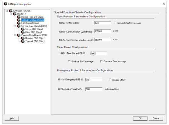
Special Function Objects
CANopen![]() A CAN-based communication system. It comprises higher-layer protocols and profile specifications. CANopen has been developed as a standardized embedded network with highly flexible configuration capabilities. defines three special function protocols such
as Synchronization, Emergency Indication, and Time-Stamp Transmission.
A CAN-based communication system. It comprises higher-layer protocols and profile specifications. CANopen has been developed as a standardized embedded network with highly flexible configuration capabilities. defines three special function protocols such
as Synchronization, Emergency Indication, and Time-Stamp Transmission.
Sync - Synchronization Object (Sync) Protocol
Emcy - Emergency Object (EMCY) Protocol
Time - Time-Stamp Object (TIME) Protocol
Synchronization Object (Sync) Protocol
The Sync Object is broadcast periodically by the Sync
Producer. The Sync-Producer provides the synchronization-signal for the Sync-Consumer. When the Sync-Consumer receives the signal they start carrying out their synchronous![]() In step or in phase, as applied to two or more circuits, devices, or machines. Contrasted with Asynchronous. tasks. The time period between Sync messages is defined by
the communication Cycle Period, which may be reset by a configuration
tool to the application devices during the boot-up process. The Sync message
is mapped to a single CAN frame with the identifier 128 by default. The
Sync message does not carry any data.
In step or in phase, as applied to two or more circuits, devices, or machines. Contrasted with Asynchronous. tasks. The time period between Sync messages is defined by
the communication Cycle Period, which may be reset by a configuration
tool to the application devices during the boot-up process. The Sync message
is mapped to a single CAN frame with the identifier 128 by default. The
Sync message does not carry any data.
Sync Protocol Parameters Configuration
The Sync Object is broadcast periodically by the Sync Producer. The Sync-Producer provides the synchronization-signal for the Sync-Consumer. When the Sync-Consumer receives the signal they start carrying out their synchronous![]() In step or in phase, as applied to two or more circuits, devices, or machines. Contrasted with Asynchronous. tasks.
In step or in phase, as applied to two or more circuits, devices, or machines. Contrasted with Asynchronous. tasks.
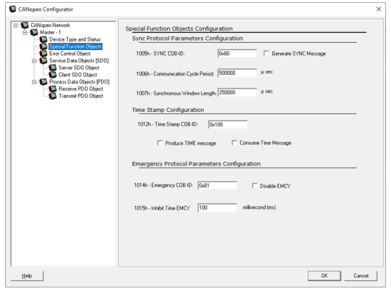
The Sync Object is broadcast periodically by the Sync Producer. This SYNC provides the basic network clock.
-
SYNC COB-ID: Default COB-ID for Sync message is 0x80; the user can change as per his requirement
-
Generate SYNC Message: Selecting this option will produce SYNC messages i.e. Node will act as SYNC producer. In the given network only one node can be SYNC producer and other nodes will act as SYNC consumer.
-
Communication Cycle Period: Enter required SYNC object cycle period in microseconds. Zero if not used.
-
Synchronous Window Length: Enter the length of the time window for synchronous PDOs in microseconds. Enter zero if not used.
Emergency Object (EMCY) Protocol
The Emergency message is triggered by the occurrence of a device internal error situation and is transmitted from an Emergency producer on the concerned application device. This makes them suitable for interrupt type error alerts. Emergency message is transmitted only once per ’error event’. As long as no new errors occurs on a device, no further Emergency message shall be transmitted. Zero or more Emergency consumers may receive these.
The reaction of the Emergency consumer is application-specific. CANopen defines several Emergency Error Codes to be transmitted in the Emergency message, which is a single CAN frame with 8 data byte.
Emergency Protocol Parameters Configuration
Emergency objects are triggered by the occurrence of a device internal error situation and are transmitted from an emergency producer on the device. Master node will consume Emergency Messages generated from several nodes. Default COB-ID for EMCY message is 0x80 + NODE ID, the user can change as per his requirement.
Emergency objects are triggered by the occurrence of a device internal error situation and are transmitted from an emergency producer on the device. Master node will consume Emergency Messages generated from several nodes.
-
EMCY COB-ID: Default COB-ID for EMCY message is 0x80 + NODE ID, the user can change as per his requirement.
-
Disable EMCY: Selecting this option will disable generation of Emergency messages.
-
Inhibit Time EMCY: Inhibit Time of a data object defines the minimum time that has to elapse between two consecutive invocations of a transmission service for that data object. It mainly avoids sending of too many messages at a time. Enter required inhibit time for the EMCY message.
Time-Stamp Object (TIME) Protocol
By means of Time-Stamp, a common time frame reference is provided to application devices. It contains a value of the type Time-of-Day. This object transmission follows the producer/consumer push model. The associated CAN frame has the pre-defined identifier 256 and a data field of 6-byte length.
Time Stamp Configuration
By means of Time stamp configuration a common time frame reference is provided to devices. It contains a value of the type TIME_OF_DAY. The identifier of the Time object is located at object index 1012h.
By means of Time stamp configuration a common time frame reference is provided to devices. It contains a value of the type TIME_OF_DAY. The identifier of the Time object is located at object index 1012h.
-
Time COB-ID: Default COB ID for Time stamp is 0X100. The user can change as per his requirements.
-
Produce TIME Message: It is used to send the time of a controller to other devices
-
Consume TIME Message: Used to accept the time from a device.
Return to the Top: CANopen Guide
Error Control Protocol
There are two types of error control protocol: Node Guarding Protocol and Heartbeat Protocol.
Node Guarding Protocol
The guarding is achieved through transmitting guarding requests (Node guarding protocol) by the NMT Master. If a NMT Slave has not responded within a defined span of time (node life time) or if the NMT Slave’s communication status has changed, the NMT Master informs its NMT Master Application about that event.
If Life guarding (NMT slave guarded NMT master) is supported, the slave uses the guard time and lifetime factor from its Object Dictionary to determine the node life time. If the NMT Slave is not guarded within its life time, the NMT Slave informs its local Application about that event. Guarding starts for the slave when the first remote-transmit-request for its guarding identifier is received. This may be during the boot-up phase or later
-
This protocol is used to detect remote errors in the network.
-
Each NMT Slave uses one remote COB for the Node Guarding Protocol.
-
The NMT Master polls each NMT Slave at regular time intervals. This time-interval is called the guard time and may be different for each NMT Slave.
-
The node life time is given by the guard time multiplied by the life time factor. The node life time can be different for each NMT Slave.
-
If the NMT Slave has not been polled
Polled - When a device is consistently asked for data, either as fast as possible or on a time basis. Normally associated with Modbus communications. during its life time, a remote node error
is indicated through the 'Life Guarding Event' service.
Heartbeat Protocol
-
The Heartbeat Protocol defines an Error Control Service without need for remote frames.
-
A Heartbeat Producer transmits a Heartbeat message cyclically. One or more Heartbeat Consumer receives the message. The relationship between producer and consumer is configurable via the object dictionary.
-
The Heartbeat Consumer guards the reception of the Heartbeat within the Heartbeat Consumer Time. If the Heartbeat is not received within the Heartbeat Consumer Time a Heartbeat Event will be generated.
The Heartbeat Protocol is used to monitor the nodes in the network and verify that
they are alive. A heartbeat producer (usually a slave device) periodically
sends a message with binary function code of 1110 and its node id![]() Usually refers to the ID of the device on a supported CAN, such as CsCAN, CANopen, etc. Each device must have a unique network ID. Also called Node ID. (COB
ID = 0x700 + node id). The data part of the frame contains a byte indicating
the node status. The heartbeat consumer reads these messages. If the messages
fail to arrive within a certain time limit (defined in the object directory
of the devices) the consumer can take action to, for example, reset the
device or indicate an error. Frame format is: COBID
+ DATA (status of node)
Usually refers to the ID of the device on a supported CAN, such as CsCAN, CANopen, etc. Each device must have a unique network ID. Also called Node ID. (COB
ID = 0x700 + node id). The data part of the frame contains a byte indicating
the node status. The heartbeat consumer reads these messages. If the messages
fail to arrive within a certain time limit (defined in the object directory
of the devices) the consumer can take action to, for example, reset the
device or indicate an error. Frame format is: COBID
+ DATA (status of node)
CANopen![]() A CAN-based communication system. It comprises higher-layer protocols and profile specifications. CANopen has been developed as a standardized embedded network with highly flexible configuration capabilities.
devices are required to make the transition from the state initializing
to Pre-operational automatically during bootup. When this transition is
made, a single heartbeat message is sent to the bus. This is the bootup
protocol.
A CAN-based communication system. It comprises higher-layer protocols and profile specifications. CANopen has been developed as a standardized embedded network with highly flexible configuration capabilities.
devices are required to make the transition from the state initializing
to Pre-operational automatically during bootup. When this transition is
made, a single heartbeat message is sent to the bus. This is the bootup
protocol.
Error Control Objects Configuration
Home > Hardware Configuration >CAN1 >Config will open the CANopen Configurator, see below. There are two types of error control protocol: Node
Guarding Protocol and Heartbeat protocol. In a CANopen![]() A CAN-based communication system. It comprises higher-layer protocols and profile specifications. CANopen has been developed as a standardized embedded network with highly flexible configuration capabilities. Network, select either of the following two options for the error control Protocol. The choice for selecting an option of error control protocol will be available only in the master node or in case of a Single slave Configuration.
A CAN-based communication system. It comprises higher-layer protocols and profile specifications. CANopen has been developed as a standardized embedded network with highly flexible configuration capabilities. Network, select either of the following two options for the error control Protocol. The choice for selecting an option of error control protocol will be available only in the master node or in case of a Single slave Configuration.
OCS supports both Node Guard and Heartbeat type of Error Control Protocol.
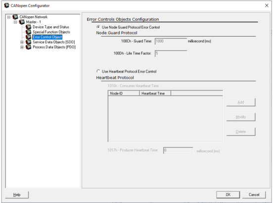
Use Node Guard Protocol Error Control: Configure Guard time and Life time factor for individual slave. Master node does not require configuration of Guard time and Life time factor. NOTE: Error Control protocol can be disabled by selecting Node Guard type and entering Guard Time & Life Time factor value as Zero.
Use Heart Beat Protocol Error Control:
-
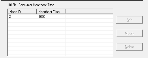
Configure Producer Heartbeat Time if given node is Heartbeat producer.
-
Configure Consumer Heartbeat Time for individual node if node is Heartbeat consumer. See image below.
NOTES:
-
Master node by default will act as heartbeat consumer.
-
Given Node can be both producer and consumer.
-
The consumer time configured must be greater than the producer time.
Return to the Top: CANopen Guide
CANopen A CAN-based communication system. It comprises higher-layer protocols and profile specifications. CANopen has been developed as a standardized embedded network with highly flexible configuration capabilities.Master Configuration
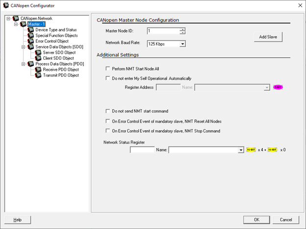
CANopen Master Node Configuration
CANopen is a communication protocol and device profile specification for embedded systems used in automation.
The XL series supports CANopen as well as the X5, RCC2414, RCC972, RCC8842, RCC1410.
CANopen Configurator is a tool integrated with Cscape used for configuration of CANopen protocol in OCS. It Supports Configuration of the CANopen Network (Master Node) or individual slave node.
Step 1: An OCS with a single CAN port supports CsCAN![]() Horner APG's proprietary network protocol that runs on the Bosch CAN network specifications. Prior to the advent of the OCS. protocol by default. User has to change the firmware to support CANopen protocol on CAN1. See also: CAN Communications
Horner APG's proprietary network protocol that runs on the Bosch CAN network specifications. Prior to the advent of the OCS. protocol by default. User has to change the firmware to support CANopen protocol on CAN1. See also: CAN Communications
Step 2: An OCS with Dual CAN ports supports CANopen protocol on CAN2.
CANopen Configuration can be done by anyone of the below ways:
-
In OCS with single CAN port select Home > Hardware Configuration >CAN1 >Config
-
In OCS with Dual CAN port select Home > Hardware Configuration > CAN2 >Config
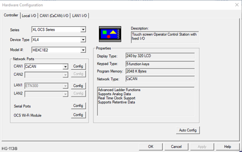
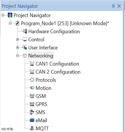
Alternately, the Hardware Configuration dialog can be found in the Project Navigator > Network Configuration or Network Configuration (CAN2) depending on the CAN port selected.
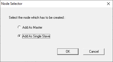
Once selected, the Node Selector will open. The user can add OCS as a CANopen master or as a Single Slave in this dialog.
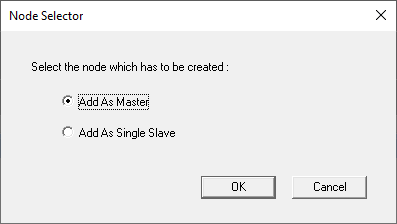
Select the Node and press OK, and the CANopen Configurator dialog will open.
The CANopen Configurator is a tool integrated with Cscape used for configuration of CANopen protocol in a Horner OCS. It Supports Configuration of the CANopen Network (Master Node) or individual slave node.
Master/Slave Relationship
At any time there is exactly one device in the network serving as a master for a specific functionality. All other devices in the network are considered as slaves. The master issues a request and the addressed slave(s) respond(s) if the protocol requires this behavior.
Select for Master Functions
Master Node ID![]() Usually refers to the ID of the device on a supported CAN, such as CsCAN, CANopen, etc. Each device must have a unique network ID. Also called Node ID.: Unique ID provided to each node, no two nodes can have same ID. The user can provide network ID in the range of 1 - 127.
Usually refers to the ID of the device on a supported CAN, such as CsCAN, CANopen, etc. Each device must have a unique network ID. Also called Node ID.: Unique ID provided to each node, no two nodes can have same ID. The user can provide network ID in the range of 1 - 127.
Network Baud Rate: The user can select the baud rate from the list box, for the given network each slave node has to be set to same baud rate as that of Master node. Different nodes at different baud rate cannot communicate with each other.
Supported Baud Rates: 50Kbps,125Kbps, 250Kbps, 500Kbps,1Mbps. NOTE: Using System Menu user can modify the Baud Rate and Node-ID, with the change in Node-ID default SDO-ID will change. But after power reset Node-ID and Baud rate will get set to value configured using Configuration tool.
Additional Master Settings
-
Perform "NMT Start Node All": Checking this option Master will send a single start command over the CANopen Network to start all the slaves.
-
Do Not "Enter My Self Operational Automatically": Checking this option will ask for trigger bit to start Master node, which will in turn start all other slave nodes in the network.
-
Do not send "NMT Start Command": Checking this option master node does not send any start command over the network, each slave must be configured for self start.
-
On Error Control Event Of Mandatory Slave, "NMT Reset All Nodes": Checking this option master node resets CANopen communication (it self and all nodes on the network) in case of error in any of the mandatory slave.
-
On Error Control Event Of Mandatory Slave "NMT Stop Command": Checking this option master node sends stop command over the network to stop the CANopen communication in case of error in any of the mandatory slave.
NOTE: In points 1 & 3, point 3 takes higher precedence over point 1 i.e., if the user selects both options point 3 will be executed. Similarly between points 4 and 5, point 4 has higher precedence over point 5.
Network Status Register
See also: EDS File
It indicates the status of CANopen Network in Master. Master and slave will have the same Network Status Register but master Node will have additional status of each Slave Node following 64-bit long Status register. One 16-bit register will be dedicated to indicate status of single slave node. NOTE: After Configuration download, firmware takes at least 10 sec to start CANopen communication with new configuration. Node will switch to pre-operational state during new CANopen configuration download, if node is master then it will send NMT command to all slave nodes to switch to pre-operational state.
Return to the Top: CANopen Guide
CANopen Slave Configuration
CANopen![]() A CAN-based communication system. It comprises higher-layer protocols and profile specifications. CANopen has been developed as a standardized embedded network with highly flexible configuration capabilities. is a communication protocol and device profile specification for embedded systems used in automation.
A CAN-based communication system. It comprises higher-layer protocols and profile specifications. CANopen has been developed as a standardized embedded network with highly flexible configuration capabilities. is a communication protocol and device profile specification for embedded systems used in automation.
The XL series supports CANopen as well as the X5, RCC2414, RCC972, RCC8842, RCC1410.
CANopen Configurator is a tool integrated with Cscape used for configuration of CANopen protocol in OCS. It Supports Configuration of the CANopen Network (Master Node) or individual slave node.
Step 1: An OCS with a single CAN port supports CsCAN![]() Horner APG's proprietary network protocol that runs on the Bosch CAN network specifications. Prior to the advent of the OCS. protocol by default. User has to change the firmware to support CANopen protocol on CAN1.
Horner APG's proprietary network protocol that runs on the Bosch CAN network specifications. Prior to the advent of the OCS. protocol by default. User has to change the firmware to support CANopen protocol on CAN1.
Step 2: An OCS with Dual CAN ports supports CANopen protocol on CAN2.
CANopen Configuration can be done by anyone of the below ways:
-
In OCS with single CAN port select Home > Hardware Configuration >CAN1 >Config
-
In OCS with Dual CAN port select Home > Hardware Configuration > CAN2 >Config

Alternately, the Hardware Configuration dialog can be found in the Project Navigator > Network Configuration or Network Configuration (CAN2) depending on the CAN port selected.

The initial step in CANopen configuration is the Node selector. User can add OCS as a CANopen master or as a Single slave in this dialog.
Select the Node and press OK, and the CANopen Configurator dialog will open. The CANopen Configurator is a tool integrated with Cscape used for configuration of CANopen protocol in a Horner OCS. It Supports Configuration of the CANopen Network (Master Node) or individual slave node.
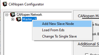
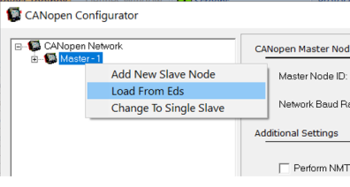
Right-click on Master Node tree to add additional slaves (as shown)
-
Add New Slave Node: Select to add New slave Node to the Master configured.
-
Load From EDS: Select to Load Master Device Type and status from EDS File.
-
Change To Single Slave: Select to change from Master configuration to Single Slave Configuration. See Single Slave Configuration
Add New Slave Node
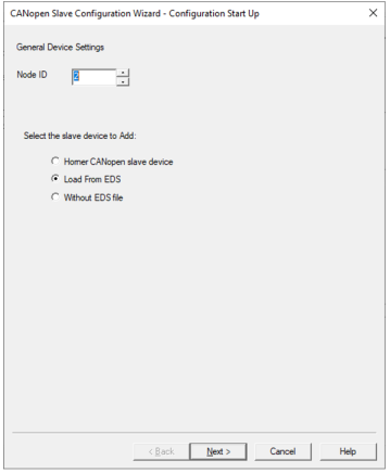
On selecting Add New Slave Node, CANopen Slave Configuration Wizard will display as below:

NOTE: It is possible to configure up to 64 PDO’s from Cscape whereas only 16 PDO’s can be reconfigured by master during RUN time.
Select the Slave Device to Add
-
Horner CANopen Slave Device: Select this option to add HORNER OCS as an CANopen slave device.
-
Load from EDS: Select this option to add slave device, by loading device specific EDS file.
-
Select Vendor, Devices and Profile option if the EDS file is already located in C:\Program Files (x86)\Cscape\EDS\CANopen\EDS
-
If the EDS file is located in some other location, use Browse button and select the appropriate EDS file.
-
Refer to EDS File.
-
-
Without EDS File: Select this option to add slave node without EDS file.
Slave Node Configuration Wizard
Select the Slave device to be added in CANopen slave Configuration Wizard and click OK. The next dialog displays the slave configuration related to SYNC, Timestamp and Emergency protocol.
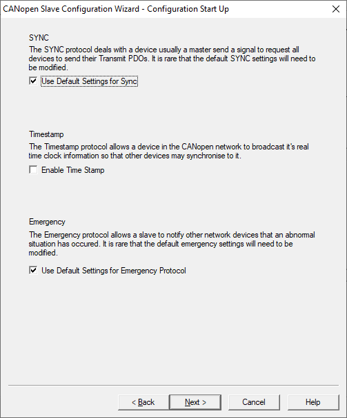
NOTE: User can modify the slave settings in the configuration wizard setup or it can be done after adding slave Node also.
See also:Synchronization Object (Sync) Protocol, Time-Stamp Object (TIME) Protocol , or Emergency Object (EMCY) Protocol.
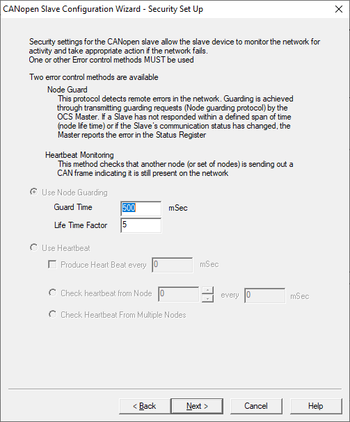
Click Next for Error Control Protocol configuration:
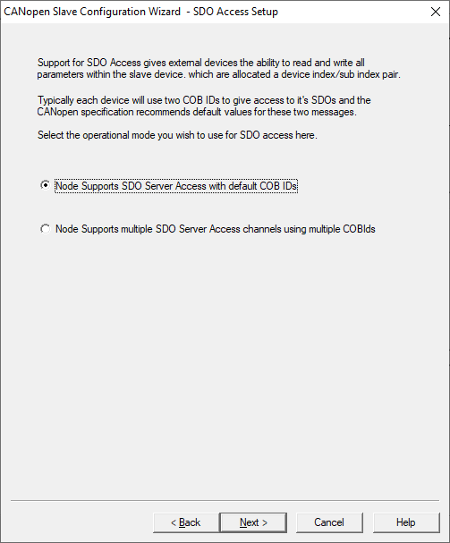
Click Next for SDO configuration:
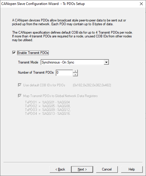
Click Next for Transmit PDO configuration:
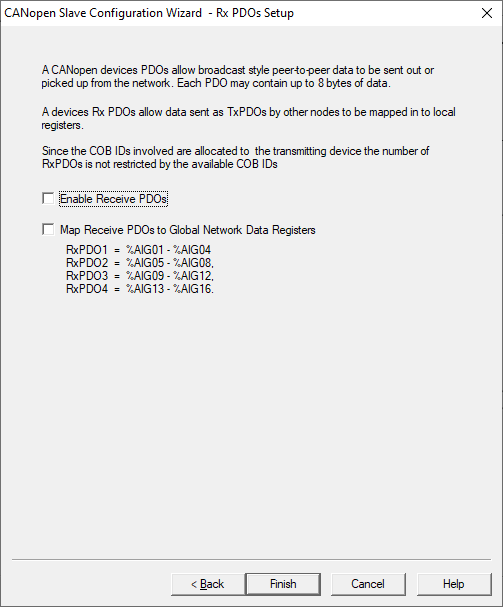
Click Next for Receive PDO configuration:
Click Back to view previous configuration dialog,
Click Cancel to cancel the slave configuration.
Click Help to open CANopen Help Document
Click Finish to close the configuration wizard.
Once the configuration setup wizard is finished, slave node will get added to the CANopen Network and it is shown as below:
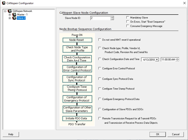
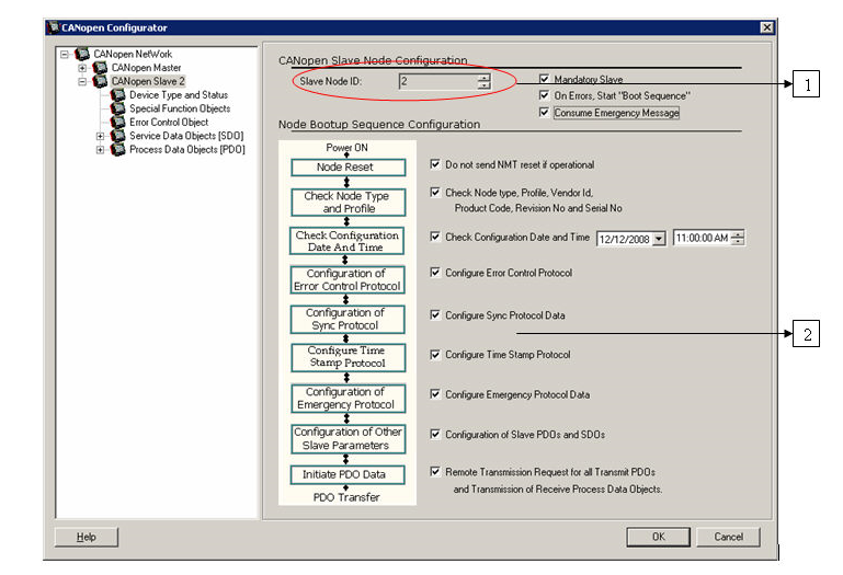
CANopen Slave Node Configuration
Slave Node ID![]() Usually refers to the ID of the device on a supported CAN, such as CsCAN, CANopen, etc. Each device must have a unique network ID. Also called Node ID.: Unique ID provided to each node, no two nodes can have same ID. The user can provide network ID in the range of 1 - 127.
Usually refers to the ID of the device on a supported CAN, such as CsCAN, CANopen, etc. Each device must have a unique network ID. Also called Node ID.: Unique ID provided to each node, no two nodes can have same ID. The user can provide network ID in the range of 1 - 127.
Mandatory Slave: On Selecting this option, the slave node is considered as a Mandatory Slave.
On Errors, start “Boot Sequence: Select this option if given node has to be rebooted on error.
Consume Emergency Message: Select this option if master node has to consume emergency message from this node.
Node Bootup Sequence Configuration
Master Node needs Node Bootup Sequence Configuration information to know when to configure the slave node and what all parameters need to be checked before configuring the particular slave. This is not necessary while configuring single slave, since there is no master configuration done in case of single slave configuration.
Node Reset: Do not send NMT reset if operational: On selecting this option Master will not send reset command on boot up if the node is in operational state.
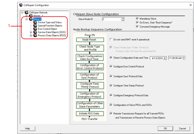
Check Node type, Profile, Vendor ID, Product Code, Revision No., and Serial No.:This option gets enabled only after loading the EDS file. Selecting this option master will check these information on network Boot-up. If any of these parameters doesn’t match then master sets error and stops configuration of given node.
Check Configuration Date and Time: Selecting this option Master node sends SDO requests to upload Date and Time of Last Configuration downloaded on network Boot-up. If Current Date and Time is different from that returned from slave, then Master Node continues with reconfiguration of selected parameters.
Configure Error Control Protocol: Selecting this option Master Node reconfigures Error Control protocol on network Boot-up (If supported in case of 3rd party slaves).
Configure Sync Protocol Data: Selecting this option Master Node reconfigures Sync Protocol data on network Boot-up (If supported in case of 3rd party slaves).
Configure Time Stamp Protocol: Selecting this option Master Node reconfigures Time stamp Protocol data on network Boot-up (If supported in case of 3rd party slaves).
Configure Emergency Protocol data: Selecting this option Master Node reconfigures Emergency Protocol data on network Boot-up (If supported in case of 3rd party slaves).
Configuration of Slave PDO's and SDO's: Selecting this option Master Node reconfigures SDOs and PDOs data.
Remote Transmission Request for all Transmit PDOs and Transmission of Receive Process Data Objects: Selecting this option Master Node sends RTR request for transmit PDOs of given slave and transmits all receive PDOs on network Boot-up.
Configure other CANopen parameters for given slaves as shown:
Configure these parameters as explained in CANopenMaster Configuration . Note: By default, without configuration download, the OCS will act as slave node.
Single Slave Configuration
Home > Hardware Configuration >CAN1 >Config will open the CANopen![]() A CAN-based communication system. It comprises higher-layer protocols and profile specifications. CANopen has been developed as a standardized embedded network with highly flexible configuration capabilities. Configurator, see below.
A CAN-based communication system. It comprises higher-layer protocols and profile specifications. CANopen has been developed as a standardized embedded network with highly flexible configuration capabilities. Configurator, see below.
OCS can act as a Single slave to communicate with any CANopen Master. User can select the configuration for single slave in the initial step of Node selector as shown below:
CANopen Configurator can be used to configure single slave. Master Node configured can be changed to single Slave with a right-click on Master Node > Change to Single Slave
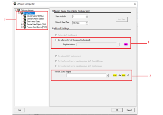
-
Select this option if operational state transition is controlled by Master
-
Configure Network Status register address
-
Configure other CANopen network parameters
NOTE: After Configuration download, firmware takes at least 10 sec to start CANopen communication with new configuration. Node will switch to pre-operational state during new CANopen configuration download, if node is master then it will send NMT command to all slave nodes to switch to pre-operational state.
Return to the Top: CANopen Guide
EDS File
CANopen![]() A CAN-based communication system. It comprises higher-layer protocols and profile specifications. CANopen has been developed as a standardized embedded network with highly flexible configuration capabilities. EDS (Electronic Data Sheet) file serves as template for different configurations for one device type.
A CAN-based communication system. It comprises higher-layer protocols and profile specifications. CANopen has been developed as a standardized embedded network with highly flexible configuration capabilities. EDS (Electronic Data Sheet) file serves as template for different configurations for one device type.
An EDS file describes:
-
Communication functionality and objects as defined in /CiA301/ and Application Frameworks.
-
Device specific objects as defined in the device profiles
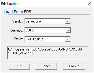
Loading EDS file: Right-click on node à Load from EDS will open EDS Loader.
Load specific EDS file using EDS loader. It will launch EDS Loader dialog box and allows selecting the vendor, Device and Profile.
After configuring EDS Loader, click OK to load the corresponding EDS file into the node. This will reset all the entries to their default values if available in the EDS file.
NOTE:
-
All EDS files for different devices are stored under Cscape à EDS folder.
-
This option is also available in the slave nodes
-
Horner supplies the following EDS files with the configuration Tool.
-
OCS_FullReg.eds
-
OCS_LtdReg.eds
-
OCS_FullReg.eds: This file contains full registers i.e about 15,500 registers and it takes about 1 - 2 mins for loading EDS file. The details of the registers range are as follows:
%R![]() Retentive 16-bit registers. - %R1 to %R9999
Retentive 16-bit registers. - %R1 to %R9999
%M![]() Retentive single-bit registers. - %M1 to %M2048
Retentive single-bit registers. - %M1 to %M2048
%AQ![]() 16-bit output registers used to send analog information such a voltages, levels, or speed settings to an attached device. - %AQ1 to %AQ512
16-bit output registers used to send analog information such a voltages, levels, or speed settings to an attached device. - %AQ1 to %AQ512
%Q![]() Single-bit output registers. Typically, these bits are connected to an actuator, indicator light or other physical outputs. - %Q1 to %Q2048
Single-bit output registers. Typically, these bits are connected to an actuator, indicator light or other physical outputs. - %Q1 to %Q2048
%AI![]() 16-bit input registers used to gather analog input data such as voltages, temperatures, and speed settings coming from an attached device. - %AI1 to %AI512
16-bit input registers used to gather analog input data such as voltages, temperatures, and speed settings coming from an attached device. - %AI1 to %AI512
%I![]() Single-bit input registers. Typically, an external switch is connected to the registers. - %I1 to %I2048
Single-bit input registers. Typically, an external switch is connected to the registers. - %I1 to %I2048
%AQG - %AQG1 to %AQG32
%QG - %QG1 to %QG64
%AIG - %AIG1 to %AIG32
%IG - %IG1 to %IG64
%T![]() Non-retentive single-bit registers. - %T1 to %T2048
Non-retentive single-bit registers. - %T1 to %T2048
%S![]() Single-bit bit coils predefined for system use. - %S1 to %S16
Single-bit bit coils predefined for system use. - %S1 to %S16
%D![]() Single-bit flags used to control or monitor display screen on units that have screens. - %D1 to %D1023
Single-bit flags used to control or monitor display screen on units that have screens. - %D1 to %D1023
%SR![]() 16-bit registers predefined for system use. - %SR1 to %SR192
16-bit registers predefined for system use. - %SR1 to %SR192
OCS_LtdReg.eds: This file contains limited number of registers i.e, 254 registers of each type and it takes 2 - 3 secs for loading EDS file. The details of the registers range are as follows:
%R![]() Retentive 16-bit registers. - %R1 to %R254
Retentive 16-bit registers. - %R1 to %R254
%M![]() Retentive single-bit registers. - %M1 to %M254
Retentive single-bit registers. - %M1 to %M254
%AQ![]() 16-bit output registers used to send analog information such a voltages, levels, or speed settings to an attached device. - %AQ1 to %AQ254
16-bit output registers used to send analog information such a voltages, levels, or speed settings to an attached device. - %AQ1 to %AQ254
%Q![]() Single-bit output registers. Typically, these bits are connected to an actuator, indicator light or other physical outputs. - %Q1 to %Q254
Single-bit output registers. Typically, these bits are connected to an actuator, indicator light or other physical outputs. - %Q1 to %Q254
%AI![]() 16-bit input registers used to gather analog input data such as voltages, temperatures, and speed settings coming from an attached device. - %AI1 to %AI254
16-bit input registers used to gather analog input data such as voltages, temperatures, and speed settings coming from an attached device. - %AI1 to %AI254
%I![]() Single-bit input registers. Typically, an external switch is connected to the registers. - %I1 to %I254
Single-bit input registers. Typically, an external switch is connected to the registers. - %I1 to %I254
%AQG - %AQG1 to %AQG32
%QG - %QG1 to %QG64
%AIG - %AIG1 to %AIG32
%IG - %IG1 to %IG64
%T![]() Non-retentive single-bit registers. - %T1 to %T254
Non-retentive single-bit registers. - %T1 to %T254
%S![]() Single-bit bit coils predefined for system use. - %S1 to %S16
Single-bit bit coils predefined for system use. - %S1 to %S16
%D![]() Single-bit flags used to control or monitor display screen on units that have screens. - %D1 to %D254
Single-bit flags used to control or monitor display screen on units that have screens. - %D1 to %D254
%SR![]() 16-bit registers predefined for system use. - %SR1 to %SR192
16-bit registers predefined for system use. - %SR1 to %SR192
Return to the Top: CANopen Guide
CAN Wiring Information
CAN Networks Basics
Power and Grounding A conductive connection between a circuit or piece of equipment and the earth. Grounds are fundamentally used to protect an application from harmful interference causing either physical damage such as by lightning or voltage transients or from circuit disruption often caused by radio frequency interference (RFI). Grounding is also for the safety of the user.
The CAN and at least the network transceivers in each node need to be powered by the CAN power supply. Equipment at each node will normally require additional power. It is highly recommended that a power supply be dedicated solely to the CAN. Using the same power supply to power controllers, I/O and other things can induce noise onto the CAN.
-
A power supply of 24VDC (+/-4%) (23VDC to 25VDC) at 16A maximum is required for use in a CAN. NOTE: This is a tighter specification than needed for most OCS units. A range of 15VDC to 25VDC is the maximum acceptable at any given node.
-
In general, each node on a network consumes 75mA of power at 24VDC, equivalent to 1.8W at 24VDC.
-
With thick cable, a single network segment can have a maximum of 8A. To use a 16A power supply, the power supply must be located in the center of two network segments.
-
Thin cable has a maximum of 3A.
-
For ideal operation, locate the power supply in the center of the network to minimize voltage drops.
-
If local codes require the local CAN power supply to be earth grounded, connect the V- power conductor to a good earth ground at one place only on the network preferably at a physical endpoint.
-
It is very important to also ground each node using the grounding studs or earth ground on all devices power connections. NOTE: This is a separate connection from the shield connection on the CAN.
Multiple power supplies can be used. This may be required if excessive network lengths or high numbers of nodes cause the network power to drop below the recommended or acceptable ranges. In this case, only one power supply must have V- connected to earth ground. The remaining power supplies need to be isolated. Do not connect the V+ connection between power supplies.
NOTE: However the CAN is wired, the V- connection (along with CN_H and CN_L) absolutely MUST be connected between every node. 2-wire CAN wiring (CN_H and CN_L only) without a continuous V- connection cannot be expected to function.
Shielding A conductive barrier that reduced the effect of external electrostatic and electromagnetic fields.
Correct shielding of the CAN is important for proper communications. Incorrect shielding can cause ground loops through the shield and actually induce noise onto the communication lines rather than shield them from it. Refer toExample of OCS Wiring and notice how the shields are connected at only one end of any network segment.
-
The shield from any given length of CAN wiring should be connected to earth ground at one point only.
-
Shields from several sections can be connected together to make larger sections, but they still must only be grounded at one point only.
-
Shields are not necessarily connected to every node. NOTE: Modules do NOT have an internal connection from shield to earth ground, even though there is a shield pin on the connector. If needed, the shield is connected straight to an earth ground in this case.
-
CN_H and CN_L are a twisted pair and are shielded separately from V+ and V- which are also a twisted pair and are shielded. Both of these shielded, twisted pairs shall then be contained together within an additional shielded casing. This is already taken care of when using the recommended Belden cable. See CsCAN / DeviceNet Cable Specifications for more details.
-
Do not use junction boxes for shield connections unless they are earth grounded, in which case only ONE of them is used to connect the shield for any given section of CAN wiring.
NOTE: Refer to the module's datasheet for CAN power and grounding at hornerautomation.com.
CAN Cable
The 5-wire, multi-conductor copper cable used in a CAN includes:
-
Two wires used as a transmission line for network communications.
-
Two wires used to transmit network power.
-
One conductor used as an EMI shield.
Cabling is available in a variety of current-carrying capacities. On a CAN, every device must, at least, power its network transceivers from the network power supply. Some devices draw all of their power from the network supply. For a CAN, thick and thin cable is used as indicated:
-
Thick cable: Use for long distances and more power. Usually used for Trunk cable.
-
Thin cable: Use for shorter distances. Usually used for drop cables or where cable flexibility is needed.
CsCAN / DeviceNet Cable Specifications
|
general specifications (e.g., Belden 3082A)
|
Two twisted shielded pairs –Common axis with drain wire in center. One signal pair (#18), blue/white; One power pair (#15) black/red. Separate aluminized mylar shields around power pair and signal pair. Overall foil/braid shield with drain wire (#18), bare*. High Speed (Vp=75% min), low loss, low distortion, data pair (to keep propagation delays to a minimum). 8 amp maximum current capacity in power pair. PVC insulation on power pair. Industrial temperature range. Nominal OD 0.48”. Bend radius (fixed) 7 x diameter (3.3”) |
|
general specifications (e.g., Belden 3084A)
|
Two twisted shielded pairs –Common axis with drain wire in center. One signal pair (#24), blue/white; One power pair (#22) black/red. Separate aluminized mylar shields around power pair and signal pair. Overall foil/braid shield with drain wire (#22), bare*. High Speed (Vp=75% min), low loss, low distortion, data pair (to keep propagation delays to a minimum). 3 amp maximum current capacity in power pair. PVC insulation on power pair. Industrial temperature range. Nominal OD 0.28”. Bend radius (fixed) 7 x diameter (1.9”) |
|
121Ω, 1%, ¼ Watt or larger wattage |
|
|
Not Supported |
|
|
Nominal 24 VDC ±4% (23 VDC to 25 VDC) |
|
|
64 nodes |
|
|
253 nodes |
|
|
0-8 bytes with allowance for message fragmentation |
|
|
Addresses verified at power-up |
|
|
CRC – retransmission of message if validity not acknowledged by recipient. |
|
|
* The drain wire connects shields within the cable and serves as a means to terminate the shield into the connector. |
|
The above Thick and Thin cables are generic types that have been tested and are known to work satisfactorily in a CAN. Other cables are available in a variety of different offerings such as FLEX, HAZ-Duty, Class I (600V), UV Resistant, etc. that may better meet the environmental requirements of your application. These, plus a multitude of premade cables that comply with the above specification are available and may work but have not been tested and verified.
Bus Length
Several factors affect the maximum length of the bus including the accumulated length of drop lines, cable type, and the network data rate. Each drop line is limited to one network, but it can have multiple nodes. A drop line cannot exceed 6m (20'). When measuring cable length, normally it is taken as the distance between the terminating resistors on each end of the trunk line and does not include the length of any drop lines. (Do not exceed cumulative drop line length.) However, if the cable length from one terminating resistor to the node at the end of the last drop line is greater, then take that length as the overall cable length. Networks exceeding the maximum total cable length or consisting of more than 64 nodes must make use of repeaters![]() A device that amplifies or adds to incoming electrical signals and retransmits them, in order to compensate for transmission losses. Repeaters can be used to add additional nodes and/or distance to the network and protect the signal against noisy environments.. Up to 3 repeaters can be used for a single network to extend the length or for a total of up to 253 nodes. A repeater must be used for every 64 nodes or every maximum length of wiring. For example, a 125KBd network running on Thick Cable can be extended from 500m to 1000m using 1 repeater, to 1500m using 2 repeaters and to 2000m using 3 repeaters.
A device that amplifies or adds to incoming electrical signals and retransmits them, in order to compensate for transmission losses. Repeaters can be used to add additional nodes and/or distance to the network and protect the signal against noisy environments.. Up to 3 repeaters can be used for a single network to extend the length or for a total of up to 253 nodes. A repeater must be used for every 64 nodes or every maximum length of wiring. For example, a 125KBd network running on Thick Cable can be extended from 500m to 1000m using 1 repeater, to 1500m using 2 repeaters and to 2000m using 3 repeaters.
CAN Baudrate vs. Total Cable Length
Return to the Top: CANopen Guide
Wiring Terminology
-
Wire/Cable: Use the proper Belden wire type or equivalent for the network as specified in the CAN Wiring Rules.
-
Shielding
A conductive barrier that reduced the effect of external electrostatic and electromagnetic fields.: Assure shields are connected at one end of a segment – they are not continuous. The FG pin on the CAN connector cannot be connected to ground pin on the power supply. Put the cable shield directly to earth ground.
-
Network Length: Do not exceed the maximum length determined by the baud rate and cable type. See CAN Baudrate vs. Total Cable Length.
-
Drop Length: Total drop length for each drop should not exceed 6m (20 feet). A drop may include more than one node. The drop length adds to the overall network length.
-
Termination
A load connected to the end of a transmission line. To avoid signal reflections, it must match the characteristic impedance of the line.: 121Ω, 1%, 1/4 watt or greater wattage is recommended. 120Ω, 5%, 1/4 Watt or greater wattage may be used in most cases. Two termination resistors total should be used between CN_H and CN_L, one at each physical end of the network. -
Proper Cable Pairs Together: Data wires as a pair (white/blue). Power wires as a pair (red/black).
-
Power Supplies: 23VDC to 25VDC recommended. This is a tighter tolerance than the input power of the OCS controllers. The voltage for the CAN should not exceed 25VDC where many OCS controllers allow power up to 30VDC. If the CAN power exceeds 25VDC, it can cause damage to the CAN transceivers.
-
Grounding
A conductive connection between a circuit or piece of equipment and the earth. Grounds are fundamentally used to protect an application from harmful interference causing either physical damage such as by lightning or voltage transients or from circuit disruption often caused by radio frequency interference (RFI). Grounding is also for the safety of the user. Power Supplies: In applications requiring multiple power supplies, make sure the V- of all supplies is connected together and to earth ground at one place only. -
V- Isolation: Ensure V- is isolated from earth ground at each power supply except for one.
-
Multi-meter Network Test: It is possible to use a multi-meter to test the network for problems once it is wired, terminated and powered but before any nodes are connected. It is important that no nodes are connected if conducting this test or results may not be meaningful.
-
Check for 24VDC between V+ and V- at each end of the network and at several, if not all, of the node connections. Absence of voltage indicates a wiring problem.
-
Check for approximately 60Ω of resistance between CN_H and CN_L at each end of the network and at several, if not all, of the node connections. A measurement of 121Ω (or 120Ω) or of infinite resistance or of any other resistance indicates a wiring problem.
-
Return to the Top: CANopen Guide
CAN Wiring Rules
-
Wire the CAN in a Daisy-Chained Topology or Trunk or Drop Line Topology fashion.
-
The two nodes at the physical end-points need to have 121Ω, 1%, ¼ Watt terminating resistors connected across the CN_L and CN_H terminals. It is possible to get away with 120Ω, 5%, ¼ Watt resistors in many cases. No more or less than two terminating resistors should be used. Terminating resistors should NOT be used anywhere else on the network.
-
Use data conductors (CN_L and CN_H) that are 24 AWG
A standard system used for designating the size of electrical conductors. Gauge numbers have an inverse relationship to size; larger numbers have a small cross-sectional area. However, a single-strand conductor has a larger cross-sectional area than a multi-strand conductor of the same gauge so that they have the same current-carrying specifications. shielded twisted pair for “thin cable” and 18 AWG shielded twisted pair for “thick cable.” They must also have 120Ω characteristic impedance. In typical industrial environments, use a Belden wire #3084A (“thin”). Use #3082A(“thick”) for network cable lengths greater than 100 meters. Place data conductors (CN_L and CN_H) into a twisted, shielded pair together (Blue/White pair). -
Use power conductors (V- and V+) that are 22 AWG twisted-pair for “thin cable” and 15 AWG twisted-pair for “thick cable.” Place power conductors (V- and V+) into a twisted, shielded pair together (Black/Red pair).
-
If local codes require the local CAN power supply to be earth grounded, connect the V- power conductor to a good earth ground at one place only on the network, preferably at a physical endpoint. If multiple power supplies are used, only one power supply may have V- connected to earth ground. The remaining power supplies need to be isolated from earth ground but all the V- conductors should be connected together. The V+ conductors should be separate, one per power supply.
-
For a segment of cable between two nodes, the cable shield should be connected to ground at one end of the cable segment only.
-
A CAN (without repeaters
A device that amplifies or adds to incoming electrical signals and retransmits them, in order to compensate for transmission losses. Repeaters can be used to add additional nodes and/or distance to the network and protect the signal against noisy environments.) is limited to 64 nodes (with 63 cable segments) with a maximum combined cable length of 500m (1640') at 125kBd using Thick cable. -
Up to four CAN segments, which adhere to the above rules, may be connected together using three CAN repeaters. In this manner, a CAN may be extended to 253 nodes with a total cable distance of 2000m (6560') at 125kBd and Thick cable.
Return to the Top: CANopen Guide
CAN Network Connector
CAN Port Pins
Most OCS models provide a CAN network port, which is implemented with 5-pin connectors. The CAN port allows the OCS to exchange global data with other controllers and to access remote Network I/O devices (SmartStix, Smart Blocks and Smart Rail Modules). Th port also supports pass-through communications for programming multiple OCS controllers over the CsCAN![]() Horner APG's proprietary network protocol that runs on the Bosch CAN network specifications. Prior to the advent of the OCS. network. Also, the CAN port supports J1939 Protocol Configuration and DeviceNet Communications.
Horner APG's proprietary network protocol that runs on the Bosch CAN network specifications. Prior to the advent of the OCS. network. Also, the CAN port supports J1939 Protocol Configuration and DeviceNet Communications.
CAN Ports
The OCS CAN ports implement the ISO 11898-2 physical layer and the CAN 2.0A data link layer standards. Also, since the CAN ports are powered by an internal isolated power supply, external CAN power is not required. NOTE: The CAN port does not supply power to the network.
CAN Port Wiring
Use the CAN Connector when using CsCAN or another CAN network. Torque rating 4.5 – 7 in-lbs (0.50 – 0.78 N-m)
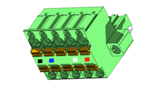
|
Pin |
Signal |
Signal Description |
|
1 |
V- |
Power - |
|
2 |
CN_L |
CAN Data Low - Blue |
|
3 |
SHLD |
Shield |
|
4 |
CN_H |
CAN Data High - White |
|
5 |
V+ |
Power + |
Cscape Programming via CAN
The CAN port supports CsCAN Programming Protocol. If a PC has a CAN interface installed (via PCI card or USB), and the PC CAN port is connected to the OCS CAN port, Cscape can access the OCS for programming and monitoring. In addition, the OCS supports single-point-programming of all OCS and other OCS/RCS devices that are connected to the CAN port network. If the PC COM port is connected to the OCS MJ1 serial port, the OCS can act as a pass-through gateway allowing Cscape to access all OCS and RCC devices that are attached to the CAN port network.
Ladder-Controlled CAN Communication
Using Put and Get Network Words function blocks, the CAN port can exchange digital and analog global data with other OCS or OCS/RCS devices (nodes) attached to the CAN port network.
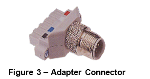
The adapter connector shown in Figure 3 is available (HE200ACC512). It allows an M12 cable, which is readily available from many sources, to be used with any of the OCS products. The use of the adapter connector and M12 cables can greatly reduce network installation time and significantly increase reliability.
Return to the Top: CANopen Guide
Wiring the Network
When wiring the network, make sure all conductors are continuous from one end to the other with the exception of the shield and the V+ conductor. The shield is grounded at one end only per cable segment. The V+ conductor is continuous to all nodes that require it unless multiple power supplies are used to power the network. When connecting nodes to the network, assure the node can be removed without disturbing communications on the system. This is accomplished if the node has a removable terminal strip or connector. However, if the node has a fixed terminal strip, a drop line should be used.
NOTE: Figures 4 and 5 are similar to one another, but Figure 5 also shows the colors of the wire.
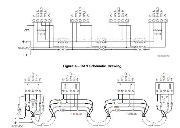
NOTE: To optimize CAN reliability in electrically noisy environments, the CAN power supply needs to be isolated (dedicated) from the primary (node) power.
Example of OCS Wiring

NOTE: To optimize CAN network reliability in electrically noisy environments, the CAN power supply needs to be isolated (dedicated) from the primary power. The CAN Shield must be attached to the panel as close to the OCS as possible.
Return to the Top: CANopen Guide
Network Layout
Nodes Any system or device connected to a network is referred to as a node.
NOTE: When setting up nodes, be aware that some units are set via software.
-
Network Baud
A data transmission unit that shows how many signaling elements or symbol changes (electronic state change) are sent per second in a line code or a digitally modulated signal. Rate: Assure the baud rate and cable length match the cable type used. -
Node ID
Usually refers to the ID of the device on a supported CAN, such as CsCAN, CANopen, etc. Each device must have a unique network ID. Also called Node ID.: Make sure there are no duplicate Node ID numbers. -
Equipment Grounding
A conductive connection between a circuit or piece of equipment and the earth. Grounds are fundamentally used to protect an application from harmful interference causing either physical damage such as by lightning or voltage transients or from circuit disruption often caused by radio frequency interference (RFI). Grounding is also for the safety of the user.: Each OCS unit must be grounded properly;-
Remove the paint from the cabinet door behind the OCS mounting nuts. Use star washers to dig into the door to insure a good ground.
-
Connect a ground strap from the door to the Earth ground in the cabinet. Cabinet door hinges do not assure a solid ground connection from the door to the cabinet.
-
CsCAN and DeviceNet both utilize a Controller Area Network, or CAN. The CAN must be wired either in a daisy-chained fashion, or Daisy-Chained Topology, such that there are exactly two physical endpoints, or using limited branching in a Trunk or Drop Line Topology. Each of the two physical ends of the network must be terminated regardless of overall length. A 3-foot network between 2 nodes may still fail if not terminated properly.
The network must never be wired in a “ring” fashion where there is no physical end to the network. The network must never be wired in a “star” fashion where there is a central connection point with branches out to each node. The sole exception to the “star” method is if each branch is no more than 6 meters (20 feet) in length. When implementing this method, terminating resistors should be placed at the ends of the two longest branches. Regardless, this is not a recommended method of wiring a CAN.
Daisy-Chained Topology
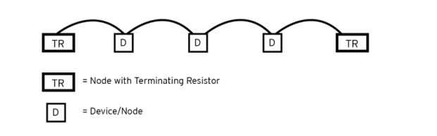
Trunk or Drop Line Topology
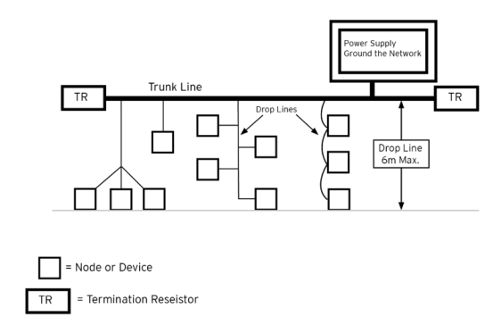
Return to the Top: CANopen Guide
CsCAN Protocol
Control Area Networks, or CAN buses, have been in use in industrial controls applications since the late 1980’s. The CAN bus itself was developed by Robert Bosch in the mid-80’s for use in the automotive industry, though it was subsequently used in several areas, including industrial automation. Allen-Bradley designed the DeviceNet protocol to work over a CAN bus, as did Honeywell with its SDS protocol. Other examples of popular network protocols that work over the same physical CAN bus wiring are CANopen and the SAE J1939 protocol.
Horner’s CsCAN (Cscape Control Area Network) is another CAN bus protocol. It was originally designed by Horner for use in conveyor controllers so that the controller from one section of conveyor could communicate directly to the previous conveyor section as well as the next conveyor section so that mail totes wouldn’t jam into each other and intersections could control “traffic”. It is, therefore, considered a peer-to-peer network as opposed to DeviceNet’s or SDS’s master-slave configuration. The physical wiring is the same as any other CAN bus, including termination requirements and distance limitations, which means nearly any wiring accessories already on the market for any other CAN bus should work with CsCAN. However, the protocol allows for operation specific to Horner OCS:
-
The ability to communicate directly from one OCS to any other OCS on the CAN bus.
-
The ability for any OCS on the CAN bus to read the inputs of any CsCAN expansion I/O.
-
The ability for Cscape to program/monitor any OCS on the CAN bus regardless of which OCS it is currently directly connected to.
As in any CAN bus, each device on CsCAN must have a unique address, or network ID. Valid network IDs for CsCAN are anything from 1 to 253. Out of the box from the factory, all OCS units are set to CsCAN ID 253. The network ID of an OCS directly corresponds to the “Local” and “Target” IDs in the Cscape status bar at the bottom right. If connected directly to an OCS, whether it is via the MJ1 port or via USB or via Ethernet, the “Local” ID is the ID of the OCS that is directly connected. The “Target” ID is the address of the controller to which this particular Cscape program is pointed. The Target address is saved with each Cscape program.
Return to the Top: CANopen Guide